
Advanced Antenna Testing for Defense and Commercial Applications
Antenna Test range Overview
TRAK TECOM’s dedicated state-of-the-art antenna test facility located in Tampa, FL provides comprehensive test and measurement services. We support the validation and production readiness of advanced antenna and positioning systems for mission-critical applications. Available for lease, the facility includes experienced antenna test support and provides test capabilities across frequencies ranging from 500 MHz to 220 GHz
TRAK TECOM’s Test Range Complex comprises of four distinct antenna ranges. These ranges provide comprehensive coverage from across a broad multi-octave frequency range and allow for testing of a variety of target sizes and geometries.
- Compact Range
- Fully Enclosed Far-Field Range
- Millimeter Wave Range
- Planar Near-Field Range
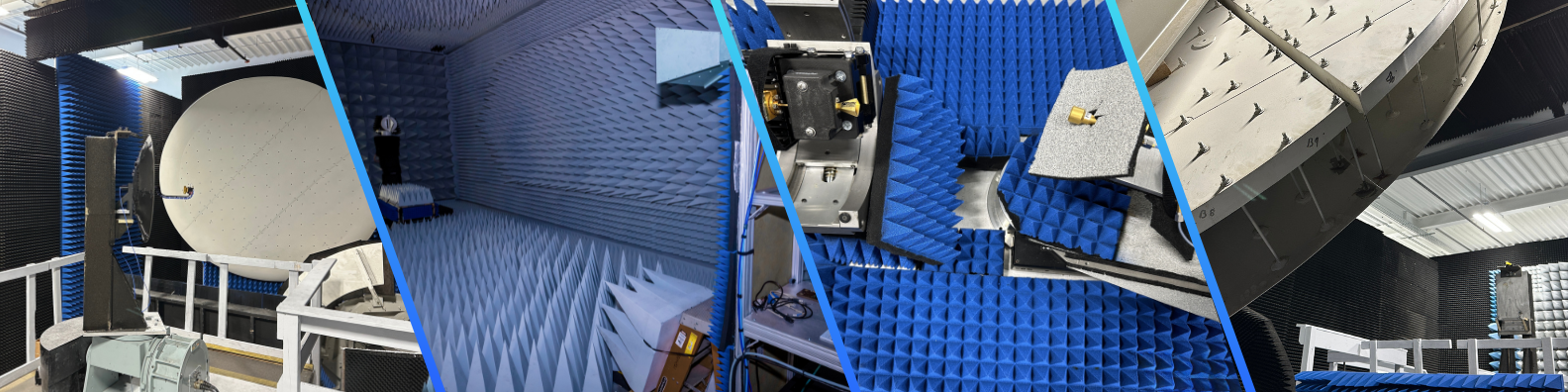
Compact Antenna Test Range
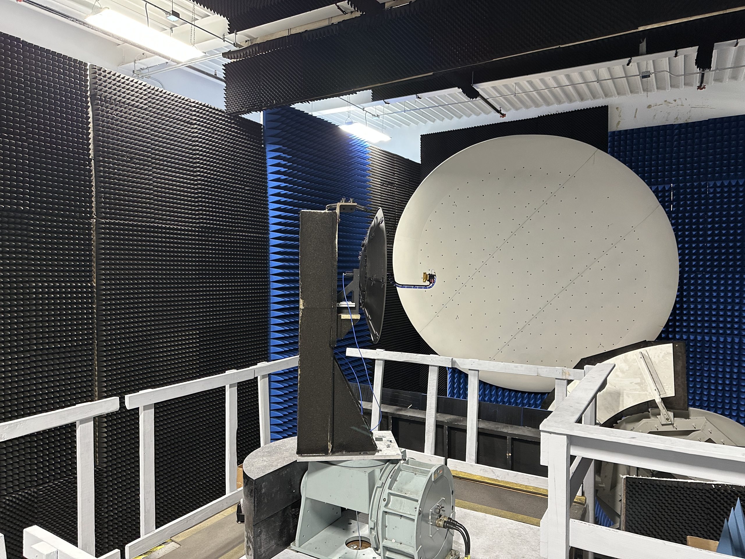
Our Compact Antenna test Range (CATR) is a semi-anechoic chamber designed to replicate outdoor conditions for accurate, repeatable antenna testing across multiple bands with high dynamic range and precision positioning.
Range Specifications
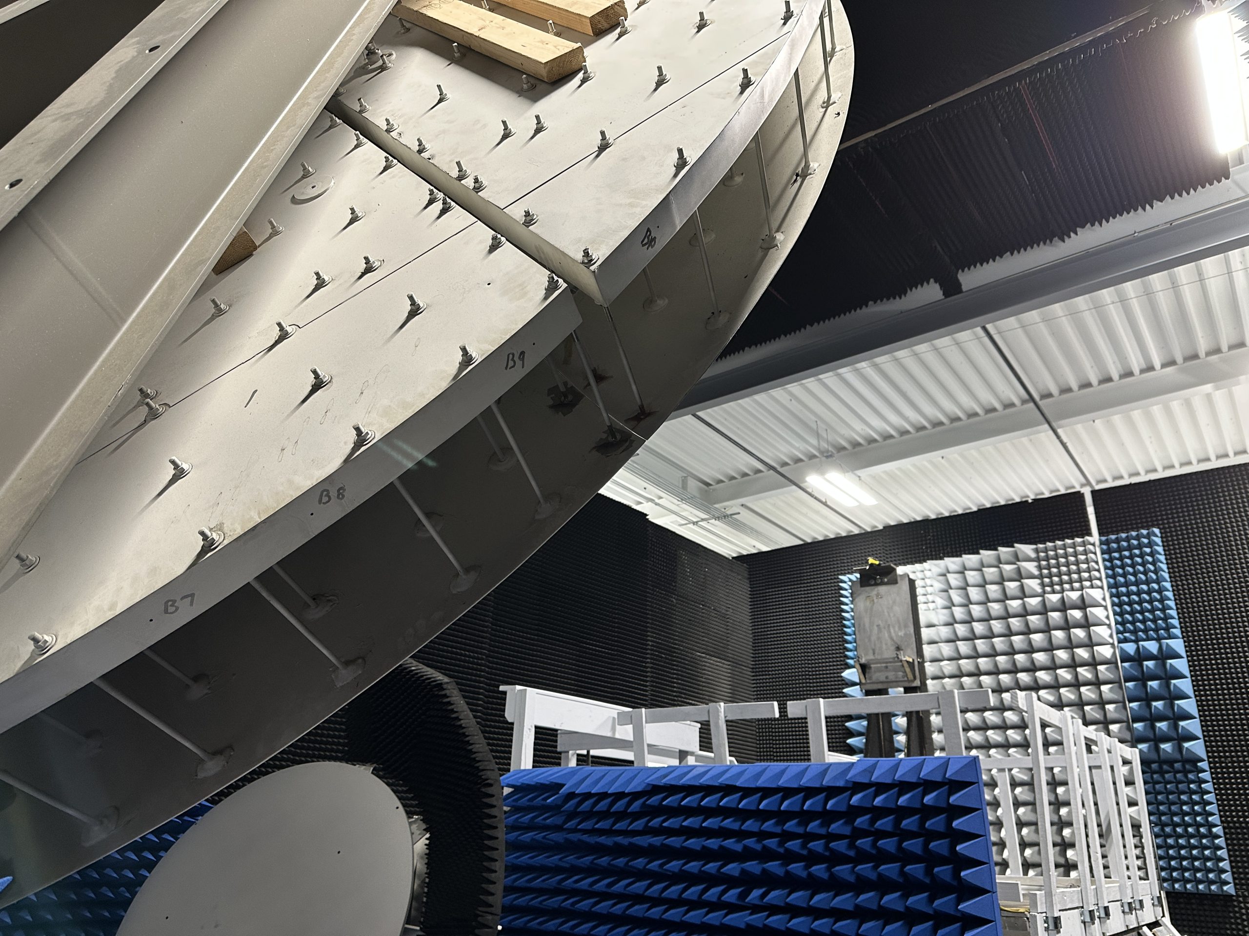
- 13.5-ft parabolic rolled-edge main reflector
- 6-ft hyperbolic offset-fed sub-reflector
- Standard quiet zone: 6 ft × 6 ft × 8 ft
-
Low-band quiet zone: 4 ft × 4 ft × 8 ft
(2–4 GHz)
Performance
- Operates across waveguide bands
- Optimized for rapid multiband antenna testing
- Distributed mixing system maximizes dynamic range and measurement sensitivity
2 - 110 GHz
Waveguide Bands
±0.01°
Positioning Resolution
13.5 ft
Main Reflector
Positioning System
Antennas under test are mounted on a metal tower equipped with azimuth over elevation axes with better than 0.01° positioning resolution. The tower sits on a walkable linear slide that precisely positions the AUT within the quiet zone. For heavier units, the slide can move to a loading position. This linear slide also provides the ability to install radomes into the range independent of the positioner to simulate true use case conditions.
Measurement System
The RF measurement system is a custom TRAK TECOM built solution using an Orbit-FR positioner controller, TRAK TECOM designed positioner axes, and NSI-MI based data acquisition software. Depending on customer preference, the AUT can be placed manually on the slide, hoisted by the gantry crane, or lifted from the floor via the elevation stage.
Fully Enclosed Far-Field Range
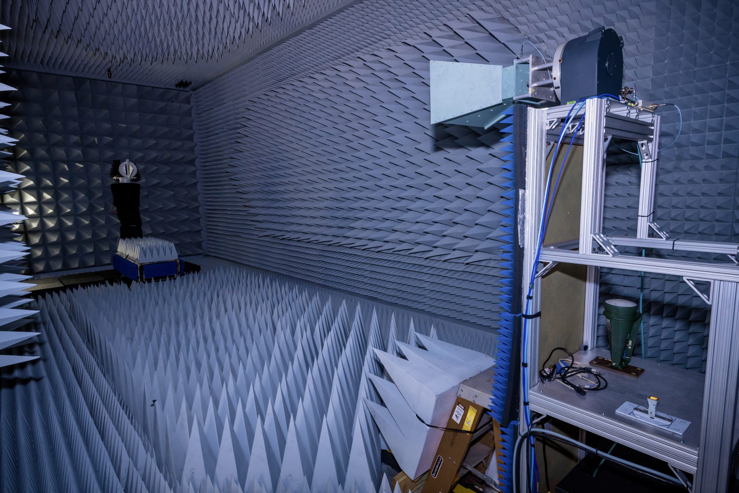
The Fully Enclosed Far-Field Range is an enclosed chamber with carbon impregnated absorber material on all six interior walls and surfaces. It is engineered for high-accuracy antenna characterization in a controlled, reflection mitigated environment. Measuring 44 ft × 16 ft × 16 ft, the range supports antenna measurements from 500 MHz to 50 GHz and provides repeatable testing for a wide variety of defense, aerospace, and commercial antenna systems.
Range Specifications
- EMI-shielded 44 ft × 16 ft × 16 ft anechoic chamber
- 26-ft source-to-AUT measurement distance
- Frequency coverage from 500 MHz to 50 GHz
- Supports large aperture antenna measurements
- Can support AUTs up to 600 lbs
Performance
- Better than ±0.01° positioning resolution
- High-accuracy phi-over-theta spherical measurements
- Designed for repeatable production and qualification testing
500 MHz - 50 GHz
Frequency Coverage
±0.01°
Positioning Resolution
26 ft
Measurement Distance
Positioning System
The antenna under test (AUT) is mounted on a precision positioning system featuring a 35-inch automated offset linear slide, roll axis, and azimuth stage. Absolute optical encoders on every axis deliver better than ±0.01° system positioning and repeatability.
The automated positioning platform enables precise antenna alignment along the boresight axis while supporting repeatable measurements across multiple antenna configurations and test programs.
Measurement System
The Fully Enclosed Far-Field Range integrates electronically synchronized roll and source axes to perform highly accurate phi-over-theta spherical antenna measurements. This configuration delivers repeatable radiation pattern characterization and supports advanced antenna performance validation from 500 MHz to 50 GHz.
Designed for qualification, development, and production testing, the system provides the precision and repeatability required for today’s mission-critical RF systems.
Millimeter-Wave (mmW) Antenna Range
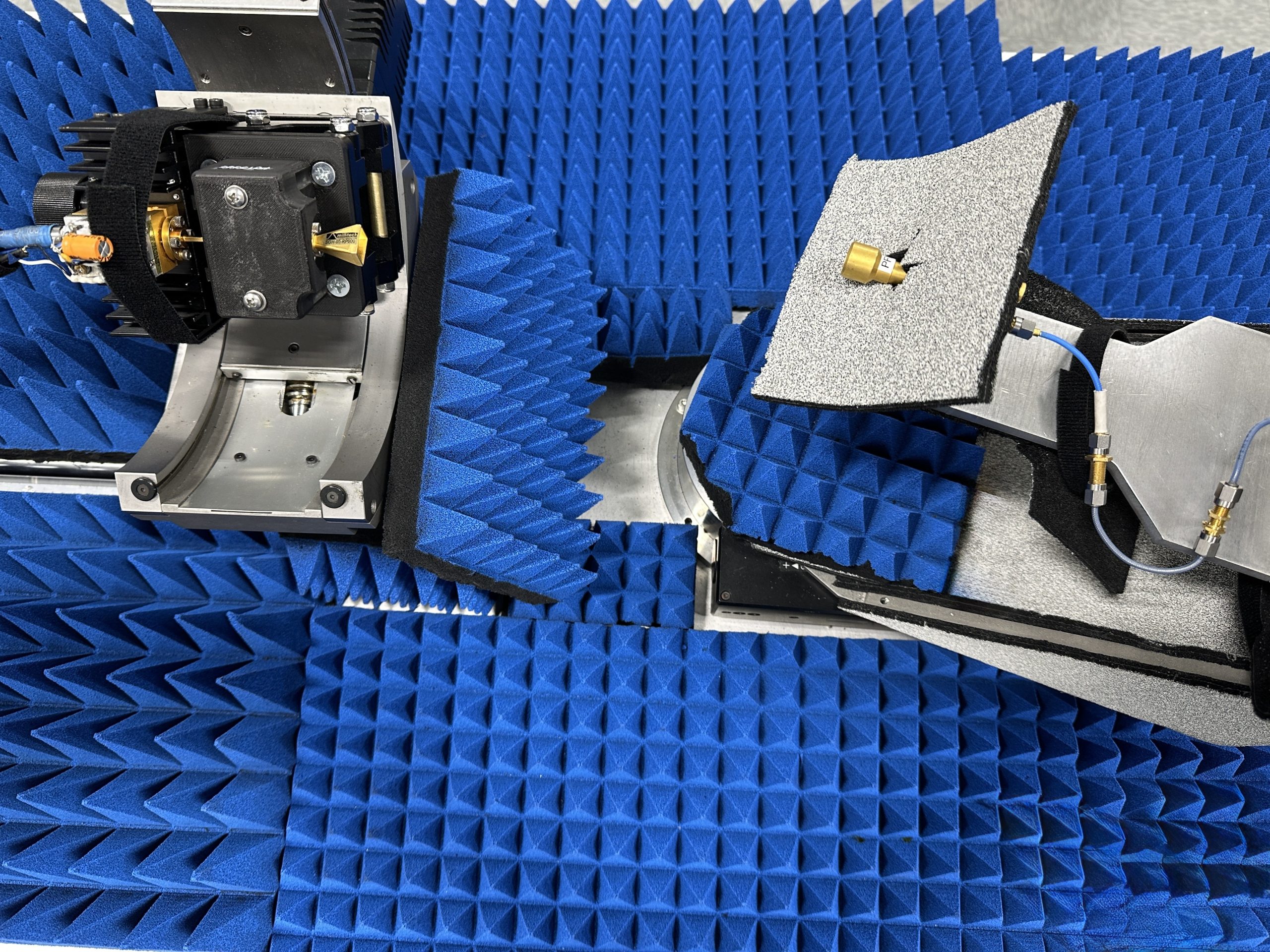
The Millimeter-Wave (mmW) Range is a variable far-field test facility engineered for ultra-high-frequency antenna characterization. Designed to overcome free-space path loss at millimeter-wave frequencies, it supports the development, qualification, and validation of reflector feed assemblies, electronically scanned-array (ESA) elements, and advanced space-based RF systems.
Range Specifications
- Variable feed-to-AUT distance adjustable from 8 inches to 6 ft
- Supports antenna pattern and performance measurements up to 220 GHz
- Designed for high-frequency reflector feeds and ESA prototype testing
- Qualified for space-based G-band radiometer testing up to 192 GHz
Performance
-
Better than ±0.005°
angular positioning
accuracy -
Configurable for
phi-over-theta or
elevation-over-azimuth testing - Generates high-density 3D co-polar and cross-polar measurement data
220 GHz
Max Frequency
±0.005°
Angular Positioning
8in - 6ft
Measurement Distance
Positioning System
The mmW Range utilizes metrology-grade positioners equipped with high-precision closed-loop stepper drives to deliver exceptional angular positioning better than ±0.005°. The adjustable feed-to-AUT distance allows the system to accommodate a wide range of antenna sizes and test configurations while maintaining measurement precision at extremely high frequencies.
Measurement System
The TRAK TECOM-designed measurement platform integrates Newport precision positioning hardware, Keysight RF instrumentation, and proprietary antenna test software to provide automated, repeatable millimeter-wave testing.
The system supports both phi-over-theta and elevation-over-azimuth measurement configurations, enabling detailed three-dimensional antenna pattern characterization. It is currently configured to qualify space-based G-band radiometer subassemblies, capturing antenna pattern and performance data up to 192 GHz.
Planar Near-Field Range
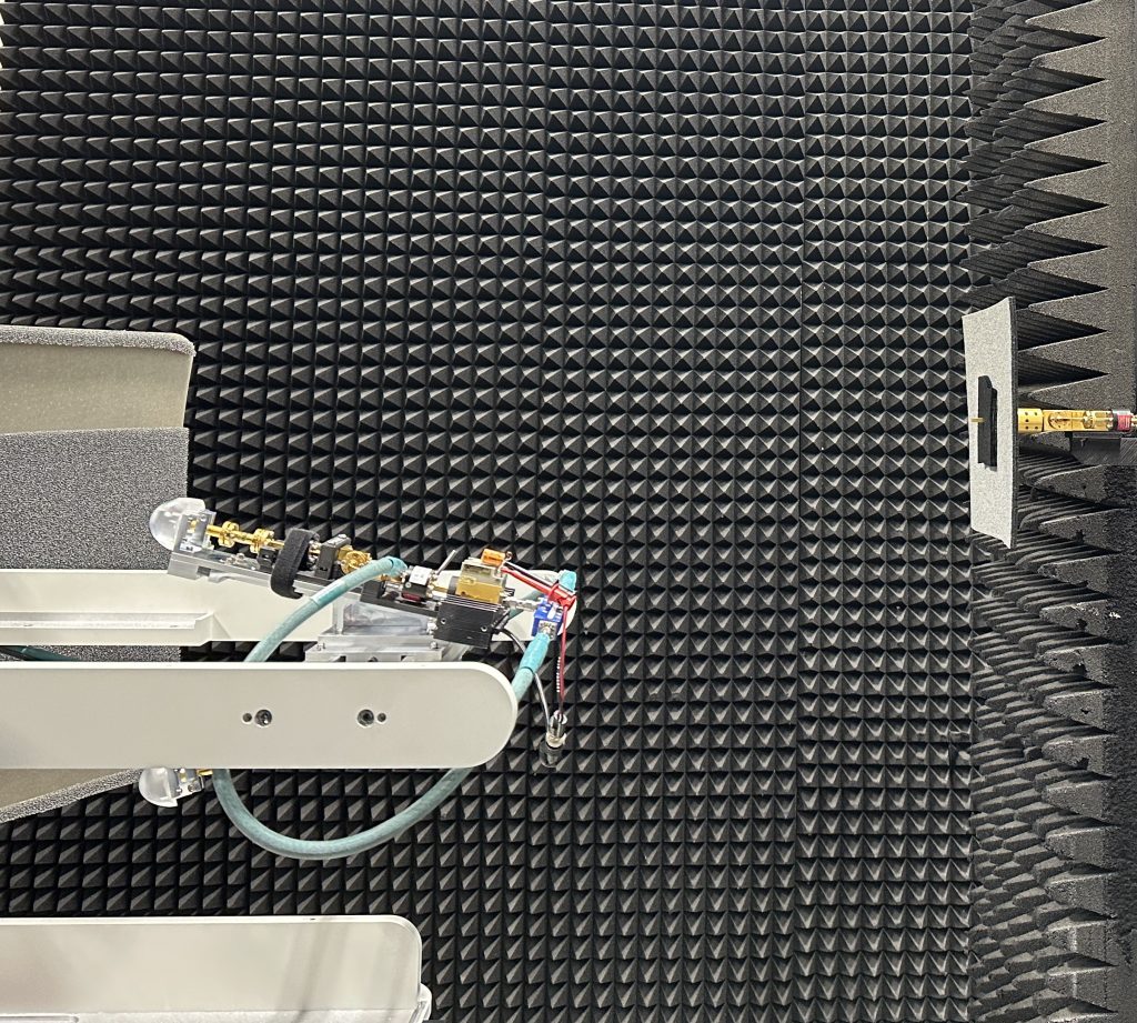
The Planar Near-Field Range is designed for high-precision antenna pattern and performance measurements of phased arrays, reflector antennas, and radomes. Featuring a 5 × 5-ft NSI-MI Technologies vertical planar near-field scanner, the system delivers fully automated testing with exceptional accuracy for antenna systems operating up to 220 GHz.
Range Specifications
- 5 × 5-ft NSI-MI Technologies vertical planar near-field scanner
- Automated probe polarization for linear and circular antennas
- Fully automated x-, y-, and z-axis scanner control
- Semi-anechoic chamber with movable walls for large radome testing
Performance
- Measures phased arrays, reflector antennas, and radomes
- High-accuracy gain and radiation pattern measurements
- Supports antenna pattern and performance measurements up to 220 GHz
2 - 220 GHz
Frequency Range
High Accuracy
Gain & Pattern Measurements
5ft x 5ft
Scanner Aperature
Positioning System
The Planar Near-Field Range features an AUT alignment positioner that precisely centers heavier antenna systems for repeatable measurements while enabling automated installation and removal. For lighter antennas, a manual mast provides a flexible mounting solution.
Measurement System
The automated probe scans horizontally (x-axis), vertically (y-axis), and perpendicular to the antenna surface (z-axis) to capture comprehensive near-field measurement data. A rotating polarization positioner measures both horizontal and vertical electric-field components, supporting fully automated testing of linear and circular polarized antennas.
Capabilities of TRAK TECOM’s Test Ranges
The table below summarizes each range’s chamber size, frequency coverage, nominal quiet‑zone, and typical antenna/object types. Detailed test conditions and handling limits are available upon request.
| Range Name | Chamber Size | Frequency Range | Quiet Zone Size | Antenna/Object Types Tested |
|---|---|---|---|---|
|
Fully Enclosed Far-Field Range |
44 × 16 × 16 ft |
500 MHz–50 GHz |
N/A |
General-purpose antennas; large aperture systems |
|
Compact Antenna Test Range (CATR) |
40 × 22 × 22 ft |
2 GHz–110 GHz |
6 × 6 × 8-ft (standard)
4 × 4 × 8-ft
(2–4 GHz)
|
Reflector antennas; Radomes; ESA production testing; polarization-sensitive systems |
|
Millimeter-Wave Antenna Range (mmW) |
Variable far-field setup |
up to 220 GHz |
Adjustable (feed-to-AUT distance: 8 in to 6 ft) |
ESA prototypes; high-frequency feeds; radiometers |
|
Planar Near-Field Range |
Semi-anechoic chamber with 5-ft × 5-ft scanner |
up to 220 GHz |
N/A |
Phased arrays; reflector antennas; radomes |
Scheduling Test Services
To schedule a test session or request a quote, contact TRAK TECOM at solutions@trak.com